Showing posts with label Sanguinololu. Show all posts

27 May, 2014

Panelolu2 and the new Marlin firmware (T3P3 fork)

Upgraded my Prusa i3 with a Panelolu 2 display/controller.

The display has an SD-card slot so no need to keep a computer running while printing. You can print G-code right off the sd-card. Saves on power consumption as well!
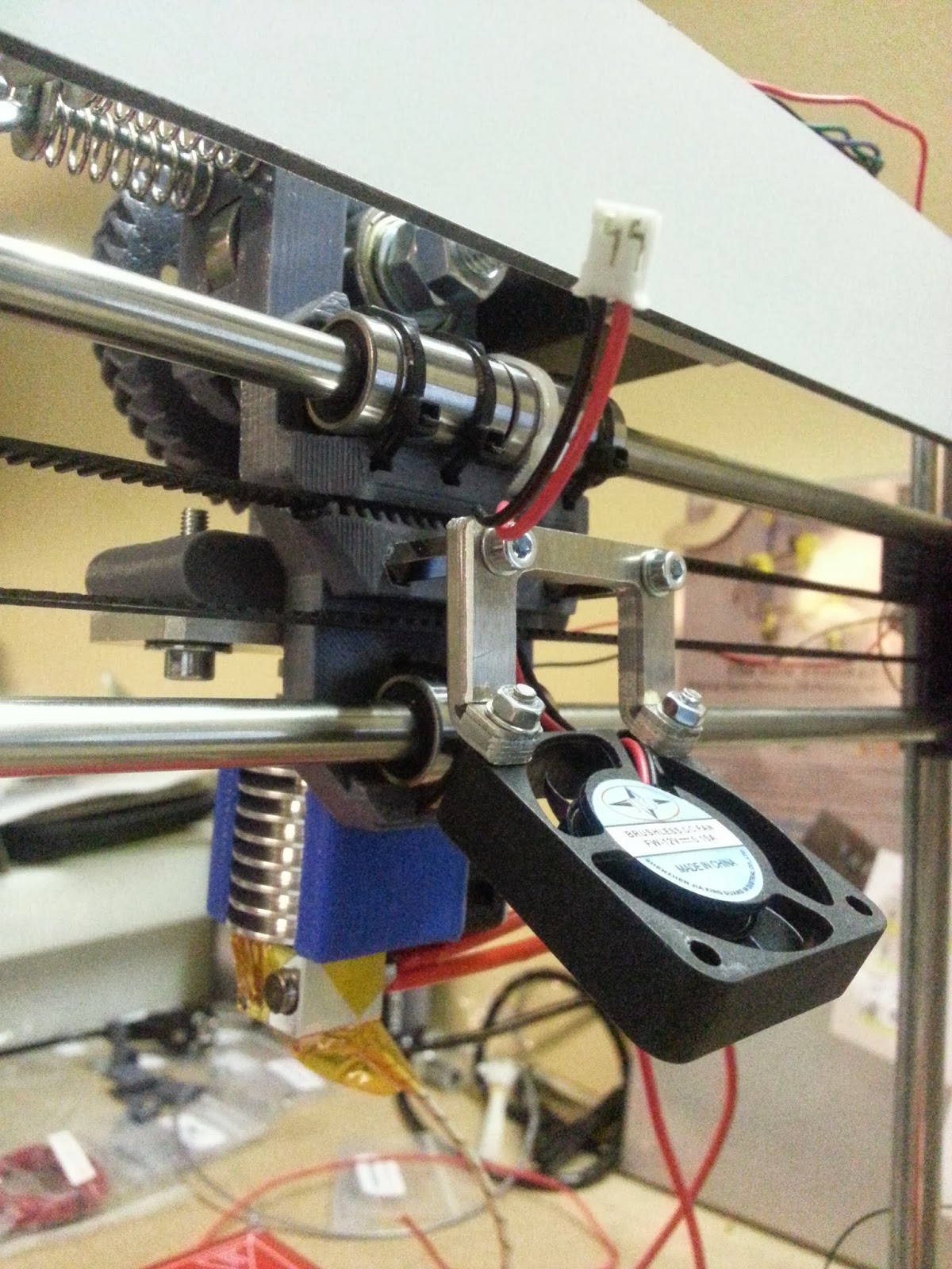
While printing you can also monitor and change the temperatures for the heatbed & extruder and change the power to the extra extruder fan (needed for PLA).

Because of the 'adapter board' you can plug the LCD into the Sanguinololu without soldering or adding components.

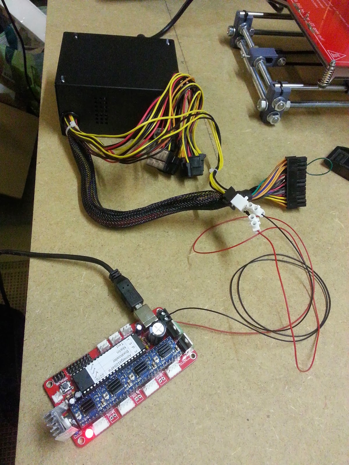
You do need to add an LCD library called Lincomatic to the Arduino IDE and flash updated Marlin firmware to the ATmega 1284P chip. The T3P3 Marlin fork can be found on GitHub.
Full Panelolu2 installation instructions are available at Think3dPrint3d 's blog. When the instructions say: "Don't use Arduino 1.x", then don't! Marlin was originally designed for Arduino 0.23 and does not work on 1.x, trust me...

I've bought the electronics from Richard @ RepRapUniverse.com.
The case for the BPC can be found on Thingiverse and can be printed yourself.

The Panelolu 2 electronics & adapter board
Printing the case for the Panelolu 2 Display
The adapter board connecting the Panelulo2 display to the Sanguinololu
A working Panelolu2 after flashing new Marlin(T3P3) firmware to the ATmega1284p

To test the new firmware and electronics I decided to print the 50mm 'torture' bridge in ABS. All seems to work fine!
Next step: Print some PLA...

21 May, 2014

Backup - Marlin Configuration.h & Slic3r Settings

I've spent days configuring and calibrating the printer to print with ABS and I'm very happy with the print quality. I have a spool with Blue PLA lying around that I want to try next. For that I'm going to install the Panelolu2 display and I need to make changes to my Marlin firmware. As I don't want to mess up anything i'm going to take a backup of my Marlin firmware and Slic3r configuration and share it here with you.

Marlin Configuration.h

for a Prusa i3 (without Panelolu2 upgrade)

Slic3er settings for ABS

I'm only listing the relevant settings that are not 'defaults' in Slic3r. To access all these settings you need to switch from Simple to Expert mode in your Slic3r preferences.

Print Settings

  • Layers & Perimeters
    • Layer Height: 2mm
    • Perimeters: 3
  • Speed
    • Bridges: 30 mm/s

Filament Settings

  • Diameter: 3mm
  • Extrusion multiplier: 1
  • Temperature:
    • Extruder
      • First Layer: 245°C
      • Other Layers: 240°C
    • Bed:
      • First Layer: 110°C
      • Other Layers: 100°C
That is all!

16 March, 2014

ATX Hack & Steps per mm calculations

Encountered an ATX power issue

MK2a heatbed @ 110° +  E3D hotend @ 240°C + powering the Sanguinololu = ATX power source wires melting!

So I decided to solder thicker wires that feed the Sanguinololu directly to the ATX printed circuit board(PCB). Results are good, the wires get a bit hot but don't melt anymore. I also added new spacers to the bottom of the ATX to be  able to mount them to the Pusa's frame.

Next issue: the MK2a heatbed takes 30 minutes to heatup to > 100°C

So I took care of these 2 things: "create direct current paths" to spare the Sanguinololu PCB and "Balance the ATX power supply"...

1. Create Direct Current paths on Sanguinololu PCB

A (modified) quote from cobrageek on the Reprap Forums on this subject:
The pads and traces on the Sanguinololu board are not robust enough to handle the high current involved when controlling the heated bed with the dedicated mosfet. If left as is, the board will heat up in this area, could be damaged and the plastic connectors discolored.
To fix, simply add a direct current path by way of (preferably insulated) wire:
  • from the 12v input to the 12v pins on the Heated Bed (HB) connector; 
  • from the center pin of the HB mosfet to the two ground pins on the HB connector;
  • from the ground pin on the mosfet to the ground input of the board (probably the ground side of the 12v connector)

2. Balance the ATX power supply:

To have a strong and steady 12V on the heatbed and hotend, you need to 'put a load' on the ATX +5V output.
To 'put this load' connect a 12 Volts 50 Watt light bulb to the +5V and GND of your ATX supply.
Check the detailed explanation on 'Balancing the ATX power supply' by Triffid Hunter.


UPDATE: The heatbed now reaches 100°C in 8 minutes (instead of 30 minutes).

Steps per mm calculations

To calculate the Steps per Milimeter for my stepper motors I used the formulas in Triffid Hunter's calibration guide to create a little excel sheet. You could also use Josef Prusa's online reprap calculator to calculate the steps per mm.

I get these results (for now) that I need to configure in my Marlin firmware:
(In "Configuration.h" the variable: DEFAULT_AXIS_STEPS_PER_UNIT {80,80,2560,674.6521728} )

Edit: I have 5mm threaded rods for my Z-axis so there are 4000 E steps for 1mm (and not 2560!)

09 March, 2014

First print

To test the mechanics, the electronics and my Marlin firmware configuration I decided to print my first STL file and see what happens...

  • Material: ABS
  • Hotend: 230°C
  • Heatbed: off (still one problem here!)
  • STL Slicer: Slic3r
  • Pinter Controller: Pronterface
  • Object: Calibration cube from Thingiverse


I now printed 3 callibration cubes that look good but make me aware that my stepper configuration (steps per mm) is not good yet.

06 March, 2014

Y-axis FIXED!

Thanks to some hints from the kind people on the RepRap.org forums I found out there was a bad connection on the bottom side of the PCB. Some solder bridged 2 connections due tho the short circuit I caused before(including smoke & flash). After cleaning up this bridge all electronics work fine and my X, Y and Z axis move smoothly!

This means I'm back on track and hopefully be printing something soon...!?
Next Step: Leveling the print bed

Short circuit on the Sanguinololu PCB

05 March, 2014

Uploading new Marlin firmware & fried electronics

I'm pretty sure I fried the ATmega 1284P-PU Microprocessor on the Sanguinololu board and went ahead and ordered a new one from Richard at RepRapUniverse.com. A stupid mistake that will hopefully only cost me about 15€ and some extra days before actually printing something...


In the meanwhile I fiddled with uploading new Marlin firmware configurations. I'll need to do this a couple of times while calibrating the different axis stepper motors so I thought I'd give it a try (also my Z-axis is inverted and I don't know if I need to flip my wiring or change the INVERT_Z_DIR parameter in the Configuration.h file).

At first I could not connect the Arduino IDE to my Sanguinololu because the maximum standard baud rate in Arduino is 115200 baud. After some hex value editing in the windows registry I was able to connect the Sanguinololu to the Arduino IDE at 250000 baud, the current rate configured in my Sanguinololu. (Thanks to this post from Conseils on his NorthernHope blog!)

Now I can send G-code via the Arduino IDE and flash new Marlin firmware via the Arduino IDE.
That makes me happy.

Flashed my first new Marlin Firmware configuration

03 March, 2014

Wiring done + Stepsticks driver current set + Extruder tested + Fried the Sanguinololu?

Wiring done for all three axis and the extruder stepper motors. Also the connections to both thermistors and the extruder heater and heatbed are ok. Still need to connect the fans to the ATX power source. (I connected the extruder fan to a free header on the Sanguinololu but I read this is a bad idea)

Setting the Vref to match my stepper-motor-driver configuration. My calculations don't match my measurements (calculated 2.24Volts and measured max 0.74Volts so my sense resistor value must be way off). But hey, the motors are working fine after some manual tweaking while listening to the motors' sound. I'll check what went wrong with the calculations later to fine tune the driver current...

This video shows the X & Z axis move during a test with Pronterface (the Z-axis moves really slow, this is normal).


Another milestone in the building process: To test the extruder I heated up the hotend gradually to 290°C and meanwhile extruded some blue PLA using Pronterface.


Open issues that need to be looked at:

Z-axis & Extruder inversion
The Z axis goes UP while going to the home position in Pronterface. Also the exdruder retracts while it's supposed to extrude and vice versa. So I need to reverse my stepper wiring from ABCD to DCBA or change the inversion setting in Configuration.h in the Marlin firmware and upload it to the Sanguinololu again.

Whoooops, I think I might have fried the Sanguinololu board :/
While fine tuning the driver current for the Y-axis i made a short circuit with my multimeter. Now my Y-axis won't move properly. Just when everything was going so good. Stupid me! 


26 February, 2014

Sanguinololu ATX Powered & USB connected to Pronterface

The Sanguinololu board is powered by a 400 Watt ATX power supply.
You really need to short circuit ATX pin 16(green) to ground(black) to enable power(!PWR_ENABLE) on the 4 pin connector.
The USB Connection goes to to a Virtual Serial COM port on the PC.


Started up Pronterface and successfully connected to the "printer" (still need to do all the wiring) using COM port 3 with a 250000 baudrate

The smoke test didn't cause actual smoke so i'm happy!


The Electronics: Sanguinololu with Polulo stepper drivers

The Electronics: a Sanguinololu controller and 4 Pololu Stepper drivers (one for each axis X,Y&Z and one for the Extruder Stepper motor). The Polulo drivers shown here are Ice Blue Stepsticks.

Here the Pololus are mounted on the Sanguinololu. Let's hope we don't blow these up when powering up the Sanguinololu.

Next step: wiring - extend and route all wires to the Sanguinololu board.
(and finding out where the mechanical endstops go for each axis.

This is the Sanguinololu wiring schema:

Mounted an extra Fan needed for printing PLA, not needed for printing ABS.